Import and export
Open 3D or DXF files in Atelier, and export your parts to other software.
Atelier opens files from other software and exports your parts in common formats.
Formats
| Format | Import | Export | What it’s for |
|---|---|---|---|
STEP (.step, .stp) | Exact solid | Yes | Exchange with CAD software. |
| STL | Mesh | Yes | 3D printing; binary or ASCII. |
| OBJ | Mesh | Yes | Reuse polygon models with separate objects or groups. |
| 3MF | Mesh | Yes | 3D printing, with colors. |
| glTF, GLB | Mesh | Yes | Show the model in a 3D scene. |
| PNG | No | Yes | Make an image of the model. |
| DXF | New sketch | One sketch | Exchange a 2D drawing, for example for cutting. |
| SVG | No | One sketch or a drawing | Print or share a dimensioned drawing. |
Atelier (.atelier, .json) | Copy of the project | Yes | Keep or share an editable project. |
Other formats aren’t accepted. On export, STEP, STL, OBJ and 3MF are in millimeters; glTF and GLB, in meters.
A mesh is a surface made of triangles. Once imported, it stays a mesh: you can move it, copy it, measure its vertices and change its appearance. Operations such as fillets need a solid. Repair mesh offers faceted conversion for one closed outward shell of at most 2,000 triangles, without recovering curved surfaces.
Import a file
Open the Import a file window:
- press S, then choose Import a file;
- or open the project menu by clicking the project name at the top left, then choose Import a file.
Drop your file on the Choose a file or drop it here area, or click it.
Choose the destination: Import here or New project.
Click Import into project or Open file.
| Destination | Effect |
|---|---|
| Import here | Adds the file to the open project. Ctrl/Cmd+Z undoes it. |
| New project | Opens a new project, named after the file. |
If your glTF has separate .bin files, add them with Add associated files. A file can be up to 100 MB.
New STEP file imports create one exact body per solid, each at its original position. A part the file places several times is imported once; its other occurrences become its instances. Bodies keep the file’s names, the name of their occurrence when it has one (a reference designator such as U3), otherwise their product’s; the solids of a product made of several are numbered, as in Header · 2. Each body takes its solid’s color, or the color covering most of its faces, with a matte finish; faces the file colors otherwise keep their own color, such as the blue tongues of USB 3.0 ports or the gold pads of a board. They keep it after an operation that trims or moves them, while faces an operation creates take the body’s color. The file’s sub-assemblies, and each product made of several solids, become folders in Objects, up to 200: deeper ones stay in the folder above. Bodies without a name in the file are named after it, such as Bracket · Part 1. You can select, modify and export each body separately. An old project’s existing STEP import feature keeps its original combined body; reopen the source STEP as a new file to separate it.
Exact solids and surfaces are imported separately; each must pass its geometric validation, and the separated sources must fit the operation-count and project-size limits. A file containing an invalid part is rejected atomically; no partial model is inserted.
In Assembly, click Import in the dock: each body in the file becomes a part. DXF isn’t accepted there. See Assemblies.
STL and OBJ meshes
Choose Mesh file unit before importing: Millimeters, Centimeters, Meters or Inches. These formats do not reliably declare their unit. Atelier converts coordinates to millimeters without recentering the parts.
- STL accepts binary and ASCII files. Named ASCII
solidblocks become separate bodies. A binary STL becomes one body, even when it contains disconnected pieces; binary STL has no object hierarchy. - OBJ keeps object/group partitions, their positions and vertex RGB colors. Triangle faces and simple planar polygons, including concave polygons, are accepted. Non-planar or intersecting polygons must be triangulated in the source software. OBJ material libraries and image textures aren’t imported; point/line geometry is listed in the import warnings. Freeform curves and surfaces are rejected.
- In Measure, click near a triangle corner to select that mesh vertex, then another vertex, a CAD element or an origin reference. The properties panel also shows the mesh’s X/Y/Z dimensions and its approximate volume when closed. Whole-mesh minimum distances and mesh face areas aren’t supported.
- Meshes remain usable as visual references, can be placed and copied, and can be exported to STL, OBJ, 3MF, glTF or GLB. Bounded faceted conversion is an explicit Repair mesh action. Save an
.atelierfile to keep the parts and their names.
The project can contain at most 250,000 imported triangles; each import is limited to 100 MB. Invalid coordinates, incomplete files and unsupported surface geometry stop the import. Zero-area triangles are removed with a warning; a body consisting only of these triangles is rejected. An open mesh can still be imported, so check its closure before printing.
Export
Click Export, at the top right of the editor.
Choose a format, for example STL (“3D printing”).
Adjust the options if needed.
Click Export. The file downloads.
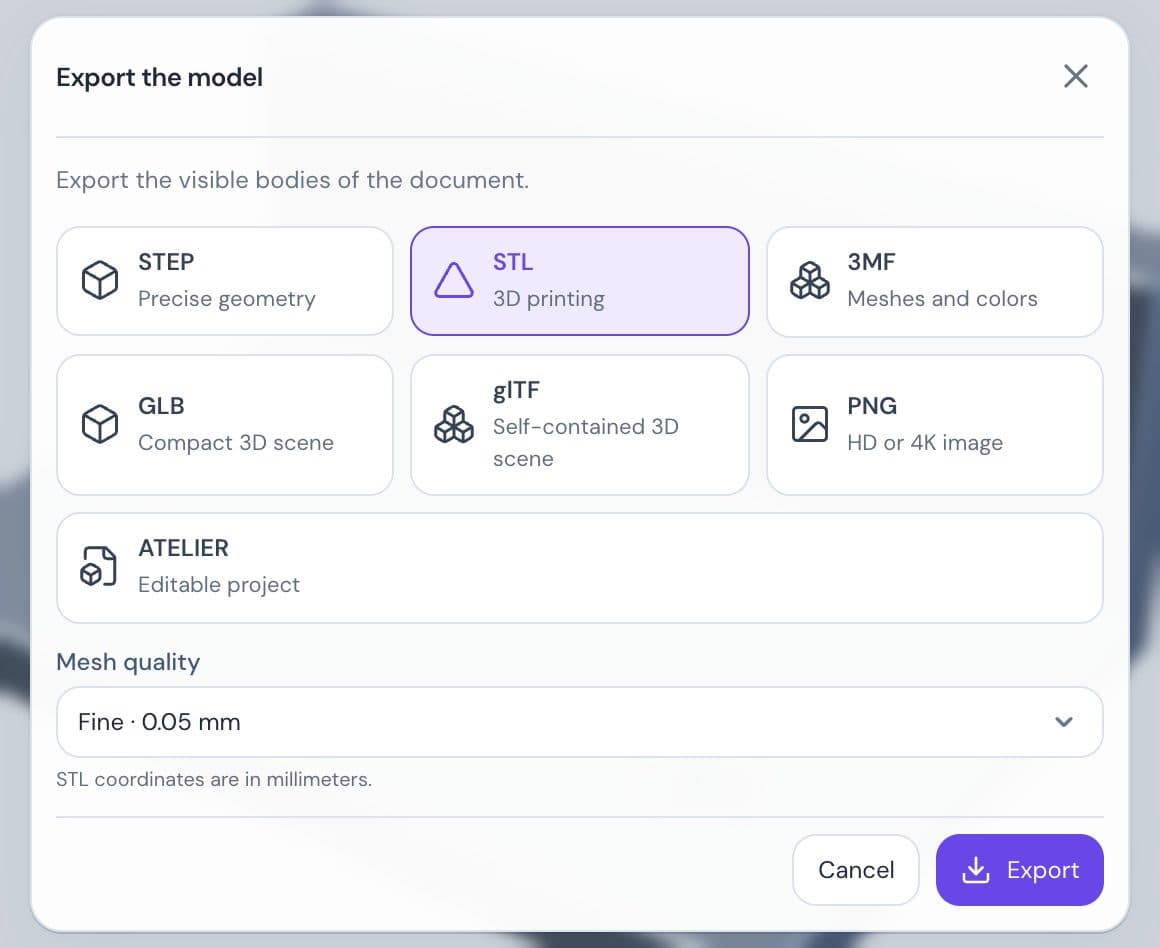
Atelier exports the selected bodies, including any hidden body that remains explicitly selected. With nothing selected, it exports all visible bodies.
| Format | Options |
|---|---|
| STL, OBJ, 3MF, glTF, GLB | Mesh quality: Standard, Fine, Very fine or Custom. The finer the mesh, the larger the file. |
| PNG | Image resolution, Transparent background, Include edges, Fit the model automatically. |
STEP accepts solids and exact surfaces. A surface must be thickened or closed before STL/3MF export. If the export contains a mesh, the STEP card is grayed out.
Check the envelope and prepare parts
For STL, OBJ or 3MF, enable Check a custom printing volume. Enter the X/Y/Z dimensions and Margin on each of the six sides. The report compares the exported group’s bounding box, with its current pose and spacing, to the usable volume. Solids use precise CAD bounds and meshes use their vertices; assembly poses are included. Excess is reported per axis. A fit means a shared translation is sufficient in that orientation, not that the parts are already on a bed.
This setting is temporary and remembered between openings until the editor closes. It does not change or block export. The check does not verify bed contact, supports, collisions or printability.
To orient each part, use Move/copy on each body before exporting. After rotation, From the origin with Min Z = 0 puts its lowest point on XY; adjust X/Y to space the parts. These operations are saved in history. 3MF preserves separate bodies, their poses, per-body colors and imported mesh corner colors. Reimporting lets you check dimensions and colors; it does not restore CAD history. Assigning colors to individual solid faces is not available.
OBJ export
OBJ writes the selected geometry as triangles, with a separate, distinct object name for each body and explicit normals. Assembly positions are retained. Coordinates are in millimeters, Z up; choose millimeters when reopening it, since OBJ has no standardized unit field. CAD solids use the chosen mesh quality; existing mesh triangles keep their precision. This export does not include colors, materials (MTL), UVs or image textures. Use 3MF for per-body or triangle colors, or STEP for exact CAD geometry.
Check imported meshes before STL or 3MF export
The export window checks the imported meshes included in the export. It counts open edges, edges shared by more than two triangles, conflicting triangle winding and degenerate triangles. A negative signed volume is flagged only for a single closed shell with consistent winding; separate shells and cavities are not classified as reversed.
Locate defects closes the window, frames the mesh and marks the affected geometry: open edges in orange, non-manifold edges in red, winding conflicts in purple and degenerate triangles in pink. Counts cover the whole mesh; the display is limited to 2,000 markers. Close the inspection and reopen Export to download the file. The check never repairs or changes the mesh, and export remains available for open meshes. Degenerate triangles still present in a project must be removed with Repair mesh before exporting. The .atelier archive preserves the original data and history.
These checks do not detect self-intersections, overlapping bodies or insufficient wall thickness, and do not certify printability. They concern imported meshes, not the tessellation of CAD solids.
For an image, choose PNG in Export. The Appearance panel adjusts materials, lighting and background: see Appearance and rendering.
Keep a project editable
The ATELIER card (“Editable project”) creates an .atelier file: the whole project, history included. Imported outside Assembly, it opens as a new project. To use it as a backup, see Projects and saving.
Only the Atelier file stays editable
A reimported STEP gives back a solid with no history. An STL, OBJ, 3MF, glTF or GLB gives back a plain mesh. To keep editing a project, keep its .atelier file.
DXF and SVG sketches
Import a DXF
Import it like any other file. Two more settings appear:
- DXF file unit: leave Automatic · file, or choose the unit;
- Sketch plane: Top, Front or Right.
A preview shows the drawing. The DXF becomes a new sketch in Modeling, with editable curves. Only text (ASCII) DXF files are read.
Export a sketch
In Modeling, click More in the dock, then Export sketch. The command palette also lists Export a sketch (DXF/SVG).
Choose the Sketch to export, then DXF or SVG in Sketch export format.
If needed, check Include construction geometry or Include points and curve handles.
Click Download DXF or Download SVG.
Both exports use solved local sketch coordinates at 1:1 scale in millimeters. A tilted or offset support does not change the profile. Dimensions, constraints and 3D placement are not exported.
SVG keeps exact lines, circles, circular arcs and cubic Bézier curves, with separate groups for geometry, construction and points. Curves remain independent: open curves stay open, and endpoints are not automatically joined into paths. Points become 0.2 mm radius markers. The page includes a 1 mm margin; its physical dimensions and viewBox preserve one millimeter per coordinate unit. SVG import is not supported.
Custom mesh precision
STL, OBJ, 3MF and glTF/GLB exports retain the three presets and add Custom quality. Set the linear deflection from 0.001 to 1 mm and the angular deflection from 0.5 to 30°. Smaller values preserve finer curved details, including modeled threads, at the cost of more triangles and longer processing. These values control tessellation of CAD solids; imported meshes retain their existing triangles. STEP remains exact.
Custom export stops when the selected group exceeds 250,000 triangles. Choose a coarser setting or export fewer bodies. The count is checked after meshing each body; it does not cap the native mesher’s initial allocation. The existing calculation timeout still applies. Settings are remembered in the editor session, without changing the document or compensating for the printing process.