Sketches
Draw a 2D profile on a plane or a face, before giving it volume.
A sketch is a 2D drawing on a plane. Its closed profiles can then become solids.
Create a sketch
In Modeling, click Sketch in the tool dock (CREATE group).
In Choose a sketch plane, click Top, Front, or Right. Or click a flat face of the model (Alt + click for a hidden face).
Draw your profile, then click Finish.
Other ways to open a sketch:
- With a flat face selected, the sketch opens on it. Its action card also offers Sketch on this face.
- Create a sketch: on the canvas of an empty project, or from command search (S).
- Objects panel: double-click a plane under Origin planes.
Draw on an offset or tilted plane
In the sketch plane chooser, click Offset or tilted plane to open Construction plane. Choose a reference, enter Plane offset and Local rotation, then Apply to save the plane. Double-click its row under Construction in Objects to create a sketch on it.
Reuse a construction plane or axis
Run Construction plane from command search or More operations. Give it a name, choose an offset/tilted support, a midplane between parallel planes, or three points, then Apply. An offset uses the support normal before the local XYZ rotation. A support can be an origin plane, an earlier named plane, or a selected planar face.
The saved plane appears under Construction in Objects, and in the sketch plane chooser. Double-click it to create a sketch. Several sketches can use the same plane: editing its history step moves them together. The eye hides the reference without breaking its dependents. Rename, edit and delete actions are available from its row; deletion or suppression is refused while an enabled dependent needs it.
Construction axis supports an origin and direction, two points, the normal of a plane, or a selected cylindrical face. Use saved axes in Revolve, Move/copy and Pattern; saved planes also drive Mirror, Split and Draft. Consumers refer to the earlier history step, not a copy of its coordinates. An ambiguous or missing source face must be selected again explicitly.
Points entered numerically are fixed coordinates, not links to model vertices. Midplanes currently require parallel supports; a normal to a curve is not yet supported.
The sketch screen
The view aligns with the plane to start drawing. The model stays visible in 3D around the drawing. View rotation is disabled while sketching; pan and zoom remain available. Closed regions are shaded; only these can become solids.
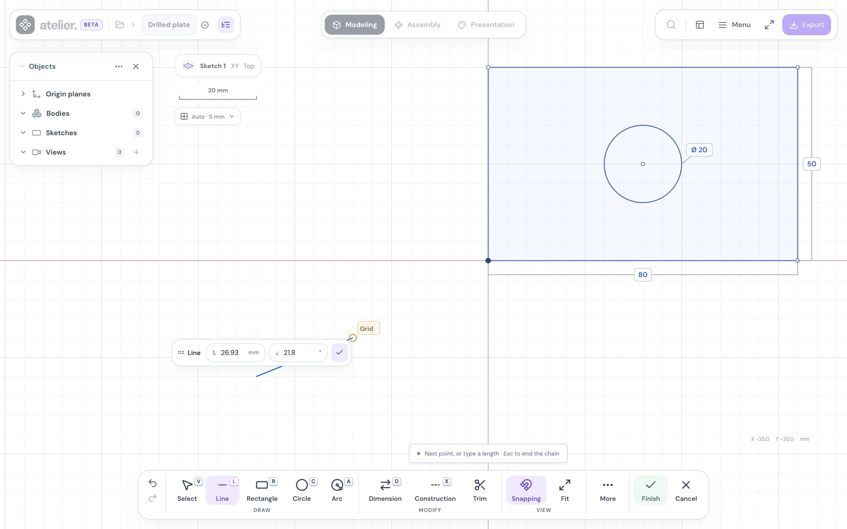
The sketch toolbar replaces the tool dock:
| Group | Buttons |
|---|---|
| Left | Undo in the sketch, Redo in the sketch |
| DRAW | Select, Line, Rectangle, Circle, Polygon, Arc |
| MODIFY | Dimension, Construction, Trim |
| VIEW | Snapping, Fit |
| More | Spline, Extend, Move/rotate, Offset, Mirror, Pattern, Project, Pan, Palette |
| Right | Finish, Cancel |
Palette opens the Sketch window, with the Dimensions and constraints list.
Drawing tools
| Tool | How to draw | Key |
|---|---|---|
| Line | Click point after point. | L |
| Rectangle | Click two opposite corners. | R |
| Circle | Click the center, then a point on the circle. | C |
| Polygon | Click the center, then the first vertex, or drag from center to vertex. | — |
| Arc | Click the center, the start, then the end (counterclockwise). | A |
| Spline | Click the start, the end, then the two tangents. | B |
To end a chain of lines, click its first point again or press Enter.
Type dimensions with the keyboard
After the first point, an input card appears: L and ∠ for a line, W and H for a rectangle, Ø for a circle. Type a value, press Tab for the next field, then Enter. Typed values become dimensions.
For a Polygon, choose 3 to 32 sides, then set its radius (center to vertex) and angle (direction of the first vertex from the sketch's X axis). The preview follows these values. Confirm with Enter or a second click; Esc cancels the polygon in progress.
The perimeter is made of editable lines. Dashed construction radii and equal-length/angular constraints keep it regular, including after saving and reopening. An entered radius or angle remains a driving dimension: edit its label to resize or rotate the polygon. Construction radii are excluded from extrusion. The side count is chosen while drawing; create a new polygon to change that count later. Undo removes the polygon and its guides together.
Snapping and grid
The pointer snaps to the origin, centers, endpoints, midpoints, alignments, intersections, and the grid. Intersections include sketch axes and reference contours. A point snapped to another point or to a midpoint stays attached to it.
- Snapping turns them all on or off.
- The grid button, at the top left, opens Grid and snapping.
- This grid remembers its visibility independently of the solid view. Purple references are limited to the plane: coplanar vertices and midpoints, and intersections with model edges. These are placement guides. Use geometry projection to retain a dependency on the model.
While drawing, hold Shift to follow horizontal, vertical or 45° directions, draw squares with Rectangle, and round lengths, diameters and polygon radii to the grid pitch. Release Shift to draw freely again. Typed values take priority. With Select, Shift keeps adding to the selection.
Navigate
- Scroll wheel: zoom.
- Pan the view: drag with the right or middle mouse button, Space + drag, or the Pan tool (H).
- Fit or Home: face the plane again and frame the sketch with its support face.
Select and delete
With the Select tool (V):
- Click a curve or a point to select it. Shift + click adds or removes.
- Click inside a closed region to select its outline.
- Drag across empty space to draw a box. Dragging right selects what is inside it; dragging left, everything it touches.
Delete erases the selection, along with its dimensions and constraints. To dimension or constrain, see Constraints and dimensions.
Edit the drawing
| Tool | What it does |
|---|---|
| Trim | Removes the clicked portion of a curve. |
| Extend | Lengthens a line or arc up to the next curve. |
| Move/rotate | Moves or rotates the selection. |
| Offset | Creates a parallel outline. |
| Mirror | Creates a mirror copy across the X or Y axis. |
| Pattern | Repeats the selection: Linear, Rectangular, or Circular. |
| Project | Copies the outline of a clicked face as construction geometry, linked to the solid. Detach breaks this link. |
Trim, Extend, and Project work with a single click. For the others: select the elements, choose the tool in More, set the values, then click Apply.
In Pattern, clear Keep copies linked to get independent copies.
Construction geometry
With nothing selected, press X or click Construction before drawing: new curves are drawn as dashed guides, including their preview. The mode stays active when you change tools. Press X again with nothing selected to return to regular drawing.
You can also select existing curves and use Construction or X to convert them or restore regular geometry. Construction geometry serves as a guide and never creates a solid.
Finish or cancel
- Finish saves the sketch and returns to solid mode. To give it volume, see Operations.
- Ctrl/Cmd+Z undoes the last action.
- Esc cancels the shape in progress, then the selection. It does not close the sketch.
Cancel discards everything, without confirmation
Cancel throws away all the work done since the sketch was opened.
Reopen a sketch
- Edit: double-click its profile in the scene, or its name in Objects → Sketches.
- Rename: F2 on its row in Objects.
- Delete: select it, then press Delete. Not possible if an operation uses it.
DXF files
An imported DXF becomes a sketch. To export: More → Export as DXF. See Import and export.