Selection and measurements
Select bodies, faces, and edges, read their properties, and measure the model.
Almost every command starts from a selection.
Choose what a click selects
In Modeling, Auto is the default: click a visible face, or aim near an edge to select that edge. The hover highlight shows the element that will be selected: a cylinder, sphere or circle the model splits into pieces, such as the two halves of a hole in an imported file, is picked whole, with no line between its pieces, and the hidden part of a hovered or selected face shows faintly through the material. Double-click selects the whole body. An imported mesh is selected as a body.
The Auto ▾ menu at the top of the canvas also offers explicit filters:
- Bodies (1): the whole body.
- Faces (2): the face under the pointer.
- Edges (3): the edge you aim at. Aim at the line, not the surface.
Changing the mode clears the selection. In Assembly, a click selects the whole part.
Select one or more items
| Action | Effect |
|---|---|
| Click | Selects the highlighted item |
| Double-click in Auto | Selects the whole body |
| Shift, Ctrl, or Cmd + click | Adds or removes the item |
| Click empty space, or Esc | Clears the selection |
| Ctrl/Cmd+A | Selects everything in the current mode |
Select with a box
Drag from an empty area of the scene:
- left to right (Enclosed items): only items fully inside the box.
- right to left (Touching items): also items partly inside.
Hold Shift, Ctrl, or Cmd as you start dragging to add to the selection.
From the Objects panel
- Hovering over a row highlights the object in the scene.
- Double-click or F2 renames a body; double-click reopens a sketch.
- Right-click a body: Fit, Rename, Hide / Show, Isolate temporarily, Show all bodies.
- The eye on a row hides the object.
Use Find in Objects from command search or the selection’s action card to reopen the panel and unfold the selected object. This reveals the row without moving keyboard focus into the tree.
The History panel follows the selection. Its heading names the object under Operations of:, and includes the face or edge scope where relevant. All operations restores the complete history; Related to selection returns to the filter.
Isolate temporarily
Right-click a visible body and choose Isolate temporarily. The canvas shows Isolation and an Exit isolation button, which stays available when Objects is hidden. Exiting restores the document’s visibility, including bodies hidden before isolation. Isolation creates no operation or undo step and ends when the document or document tab changes. Show all bodies remains a separate command that changes the saved body visibility.
Reach a hidden item
Alt (Option on Mac) + click opens the Choose an item list: everything under the pointer, from nearest to farthest. Click a row. Alt+Shift+click adds it to the selection.
Act on the selection
In Modeling, left-click selects an item. Right-click without dragging opens its action card; dragging with the right button pans the view.
- Planar face: Sketch on this face, Push/pull, Hollow out as a shell, Hole…
- Curved face: Offset this face, or Remove this hole.
- Edge: Fillet, Chamfer.
- Any item: Annotate here, Transparency…, Move/copy, Lay on XY, Move to origin…
An edge selection can immediately offer a fillet handle. A planar face offers push/pull; supported curved faces offer offset. A body selection offers movement. A suggestion does not modify the model. Drag its handle or click its dimension to begin, then use Apply or Cancel the operation.
More operations expands the rest. See Operations.
Read properties
The Properties panel describes the selection:
- Body name, editable.
- Type, then the Length of an edge or the Area of a face.
- Body volume and bounding box: Width X, Depth Y, Height Z.
- Body position: Min, Center, and Max in X, Y, Z.
- Body material (see Appearance and rendering).
With nothing selected, it shows the project’s Total volume. With several items, it shows the totals.
Atelier doesn’t calculate mass: multiply the volume by the material’s density.
Measure
Click Measure (INSPECT group) or press I.
Click an edge, a face, a body, or an orange vertex. With From, you can also start from the Origin or a plane.
Click a second item.
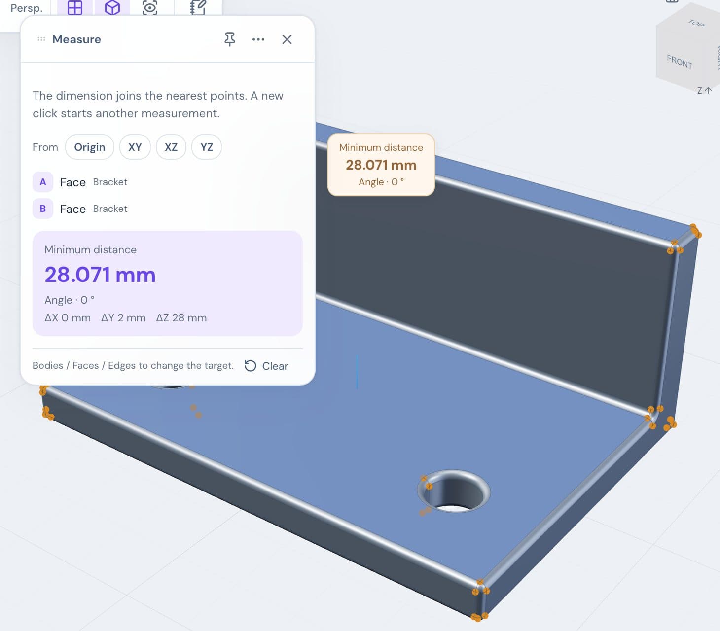
| Target | Result |
|---|---|
| An edge | Edge length |
| A face | Face area |
| A vertex | Vertex position |
| Two items | Minimum distance, with ΔX, ΔY, ΔZ |
| Two straight edges or flat faces | The Angle as well |
Switch to Edges mode to measure an edge. Clear resets, Esc finishes.
Inspect the model
- X-ray (Display or More) makes every body transparent.
- Transparency… (action card) sets the Opacity of the selected bodies.
- Section view (Display or More) cuts the view with a plane. Choose the Section plane, then drag its handle. Flip switches the side that is kept.
- Interference (More) flags overlapping solids. Under Solids to check, select the solids, then click Check the solids. For a moving joint, see Assemblies.
X-ray, transparency, and section view only change the display.
Check clearance between parts
In Interference, enable Check minimum clearance, enter Required clearance in millimeters, and Check the solids. The report compares selected solids in their current pose, including assembly placement. It lists gaps under the threshold, contacts and the closest pair. Shared solid volume counts as zero clearance, including one solid entirely contained in another. Measure in the view shows the closest points and their distance for a pair without overlap.
Choose the requirement for your process; no print compensation is assumed. Contacts are reported even at a zero requirement; equality passes within geometric tolerance. A failed measurement makes the result incomplete. This checks up to 40 CAD solids at the current pose, not wall thickness, clearance throughout joint travel, or whole-mesh distances. Settings are temporary, and changing the model invalidates the report.
Zebra and overhang analysis
Open Display → Surface analysis and choose Zebra or Overhangs. The indicator in the viewport keeps the active mode visible and lets you disable it.
- Zebra replaces the material with reflected bands. Change Stripe density and Stripe orientation, then orbit the model to inspect changes at joins. This is a visual inspection of the displayed tessellation, not a mathematical G1/G2 continuity test. CAD solids use interpolated surface normals; imported meshes show their flat triangle normals and facets.
- Overhangs uses Build direction (±X, ±Y, ±Z in world coordinates or a custom vector) and Slope limit. The arrow points from the plate toward the top of the print. Angles are measured away from vertical: 0° for a wall, 90° for a downward horizontal face. Blue means below the limit or upward-facing, yellow near the limit, red above it. The pose of each assembly part is included; moving the camera does not change its slope category.
These modes change only the view. They respect clipping and transparency; low opacity can make bands and colors harder to read. They do not calculate supports, bridging, wall thickness or intersections, and mesh winding must be consistent. Switching projects or reloading resets the analysis. Geometry exports keep the original geometry and colors. PNG captures include the current analysis; saved project thumbnails retain the normal appearance.
Add a note
Right-click the part, then choose Annotate here. Type the note and click Add note.
- Annotations (Display or More) lists the notes.
- Note visibility: All views or a single saved view.
- Drag a note to move it. If the geometry changes, click Place on the model.
Cut a housing while keeping internal parts whole
Open Section view from Display or More, then choose a plane. Under Parts affected by the section, choose Exclude and check components to keep whole, such as the motor. Include cuts only checked parts. Use search or Add selected parts for larger models.
Enter Offset in millimeters or drag the scene arrow. Inclined plane exposes azimuth and elevation; Use selected planar face places the plane on a face. Add section plane combines up to three planes. Select the plane to move and use Flip side to choose its retained half. Visible geometry is the intersection of the retained half spaces.
Under Views, beside the view cube, Save the current view keeps the camera, every plane and the part list. Saved views survive reopening and archives. PNG exports include the visible cut; STEP/STL/3MF geometry remains whole.
Plate contact and clearance over a course
In Overhangs, Measure build-plate contact compares visible bodies in their current pose to an infinite plane perpendicular to the build direction. Set offset and tolerance. Area counts triangles entirely within tolerance; point or edge contact has zero area. It does not predict adhesion or stability.
In Interference → In motion, Check minimum clearance measures a bounded course and reports a conservative bound including displacement between samples. At most 2,000 poses per pair; insufficient precision or a failed measurement remains uncertain. Solids only, at most 40.