Operations
Give your sketches volume, then modify, repeat, and combine your bodies.
An operation creates or modifies a body: extrude, fillet, hole… You start it in the Modeling workspace, and it becomes a step in the history.
Start an operation
- The tool dock, at the bottom: CREATE and MODIFY groups. More opens all the other tools.
- Actions on the local selection card, or right-click an item without dragging. Less common operations are under More operations.
- The keyboard: the key in the table below, or S to search commands.
Set and apply
Select a profile, a face, an edge, or a body.
Select an edge for a suggested fillet, a planar face for push/pull, or a body for movement. You can also start a named operation from the dock. A suggested handle is ready without creating an operation yet.
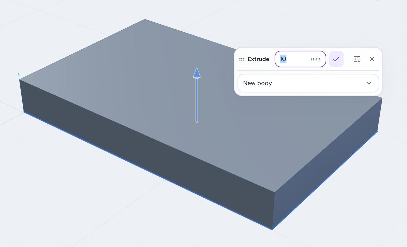
Drag the handle, or click its dimension to enter a value with its unit. This starts the operation and previews the result. Enter in this field confirms the value; it does not apply the operation.
Inspect the preview, then click Apply to add one operation to the history. Undo removes that applied operation.
Good to know
- Details opens every option, even from a zero suggestion, without calculating a default value. Back to quick settings or closing the detailed panel keeps the current operation and its values.
- For fillets, chamfers, push/pull, face offsets and shells, the handle starts at the clicked point on the edge or face and stays anchored during previews. Without a geometric click, it uses the center or midpoint.
- To change the face or edge, click it in the view.
- Esc while entering a dimension restores the value before entry. Outside the field, Esc or Cancel the operation abandons the operation.
- A zero direct offset or zero fillet radius displays the original geometry and cannot be applied as an empty operation. Invalid geometry keeps Apply unavailable; adjust the value or cancel.
- A value with a lock comes from a parameter: change it there.
- To edit an applied operation, double-click it in the history.
Snap to the model
While you drag the arrow of Extrude, Push/pull, or Move/copy, move the pointer over the model to align the depth or position with the target.
| Under the pointer | Target level |
|---|---|
| A vertex | The vertex |
| The middle of a straight edge | Its midpoint |
| The center of a circle or an arc | The center |
| An edge | The point of the edge under the pointer |
| A flat face square to the arrow | The face |
- A dot and its name show the target. A line joins it to the arrow.
- For Move/copy, the selection’s bounding-box center aligns with the target along the dragged axis. The other two coordinates stay unchanged.
- What is hidden behind the model or cut away by a section does not count.
- Handles do not snap to the body they create or modify. Move/copy excludes moved bodies; a copy can snap to its original.
- Only CAD solids provide geometric targets; imported meshes do not offer snapping vertices or edges.
- A point along a curved edge follows its displayed tessellation and may be approximate. Vertices and straight-edge midpoints retain their geometric coordinates.
- The resulting value is stored in the operation. This does not create an associative “up to face” reference: moving the target later does not change that value.
- Hold Ctrl or Cmd to drag freely, in steps.
All operations
| Operation | What it does | Where to find it |
|---|---|---|
| Create volume | ||
| Extrude E | Give a profile volume | Dock, Sketch card |
| Revolve R | Turn a profile around an axis | Dock, Sketch card |
| Loft | Connect several profiles | More |
| Sweep | Move a profile along a path | More |
| Hole | Drill a hole to an exact diameter | Card on a flat face |
| Text / engraving | Create geometric text, raised lettering or engraving on a plane | Command search |
| Printable thread | Cut a real external or internal helical thread | Command search, cylindrical face selection card |
| Modify | ||
| Push/pull Q | Move a flat face | Dock, card on a flat face |
| Fillet F | Round edges | Dock, card on an edge |
| Chamfer | Bevel edges | Card on an edge |
| Shell C | Hollow out a solid | Hollow out as a shell on a flat face |
| Draft | Tilt faces | More operations |
| Offset face | Thicken or thin a face | Card on a face |
| Remove hole | Fill a hole | Remove this hole on the hole wall, More → Remove hole |
| Move/copy M | Move, rotate, or copy a body | Dock, action card |
| Align | Lay a face on another face or on a plane | More operations |
| Scale | Resize a body | More operations |
| Lay on XY, Move to origin, Lay this face on XY | Set a body on Z = 0, center it, or turn it onto a flat face | Action card, Properties |
| Delete the body Delete | Remove bodies | Action card |
| Repeat | ||
| Mirror | Reflect a body across a plane | More operations |
| Feature pattern | Repeat a hole or additive/subtractive extrusion on one body | Command search, More |
| Pattern | Repeat a body: line, grid, circle, or path | More operations |
| Combine and split | ||
| Combine | Union, subtract, or intersect two bodies | More operations |
| Split | Cut a body with a plane | Split with a plane |
| Separate the original bodies | Suppress the body’s last union | Action card, More → Separate |
| Other | ||
| Construction plane | Create a reusable offset, tilted, midplane or three-point plane | Command search, More operations |
| Construction axis | Create a reusable direction, two-point, plane-normal or cylindrical axis | Command search, More operations |
| Linked instance | Copy a body and keep it linked | More operations |
To draw on a construction plane, see Sketches.
Extrude
- Click a region of the sketch to choose the profile. Shift + click adds or removes one.
- Set the Extrusion distance and the mode: New body, Join, or Cut. A negative distance switches to Cut.
- In Cut, Through all cuts through the whole body.
- All settings adds the Direction (One side or Symmetric · total distance), the Target body, and Flip direction.
End condition → To a plane / plane of a face uses a named construction plane or Use selected planar face as the target. Set Offset along target normal in millimeters. The target must be parallel to the sketch; it drives the extrusion after upstream edits. The operation ends on the infinite support plane, even beyond a face boundary. It does not trim to a curved/oblique face or stop at the next object. This mode replaces the numeric distance, symmetric extent and through-all option.
Revolve
- Set the Revolution angle, or drag the point at the end of the arc.
- All settings gives the Revolution axis (X, Y, or Z) and its Axis position, or Use construction axis to follow a named axis in any direction. Edit the source axis in the history to change its position or direction.
- It always creates a new body: merge it afterward with Combine.
Push/pull
The dimension next to the grip offers Offset or Total. Offset measures movement from the starting face; Total sets the final distance from a parallel opposite face that stays fixed. Switching modes preserves the current shape. Total is unavailable when no compatible opposite face is found behind the picked point.
A dashed guide connects the reference to the moving face, which remains purple throughout the preview. New operations extend adjacent planar surfaces, including slopes, and preserve prismatic holes, sketch curves extruded along the move and supported end fillets. Unsupported curved junctions and distances that collapse an edge are rejected. Previously saved operations retain their geometric behavior.
- Set the Face distance. A negative value removes material.
- Keep fillets keeps the neighboring rounds, fillets as well as the rounded corners of a sketch: they move with the face, including on the wall of a shell, or are rebuilt at their radius around the moved face. Unchecked, the face extends to the sharp edges the rounds replaced; failing that, they move with the face, and otherwise only the face itself is extruded or cut in place.
- On a curved face, Q opens Offset face. A cylinder made of several faces, such as the two halves of an imported hole, changes radius as a whole.
Fillet and chamfer
In Auto, click a visible edge: its suggested fillet handle appears at radius zero. Pull it or click the radius to enter a value. Simply selecting or hovering does not modify the part. Use Fillet explicitly when you need to choose the edges in its settings.
- Click the edges to work on. With no edge selected at the start, All edges is checked.
- Fillet: set the Fillet radius. Variable radius along the edge gives a start and an end radius.
- Chamfer: choose the Chamfer mode, Symmetric or Distance + angle. In Distance + angle, click Choose the reference face, then the face.
- Edge gone after a change? Click Repair edges.
Shell
Click the planar faces to open, or enable Closed shell to make an enclosed cavity without removing a face. Set the Wall thickness and Wall direction:
- Inward keeps the outside dimensions.
- Outward keeps the original solid as the cavity and grows the walls outside.
- Both sides divides the total thickness equally inward and outward.
Outward and both-sides modes round the exterior corners. The operation requires one connected solid and refuses impossible offsets. Thickness can follow an expression; closed and both-sides modes use the numeric field without a face handle. History, undo, persistence and exact/mesh exports retain the cavity.
Hole
- Choose the Hole type: Simple, Counterbore, or Countersink.
- Set the Diameter (mm) or use a Screw clearance preset for M2, M3, M4, M5, M6, M8, M10 or M12, in the fine, medium or coarse series. Nominal ISO 273 values come from the NBK manufacturer table. A preset fills the diameter; it does not link a screw. Counterbore and countersink head dimensions remain manual, and no print compensation is added.
- Under Hole centers, choose Coordinates on the face, then Add a center for up to 100 positions in the same frame.
- Linked sketch points uses the checked points of the Position sketch, their solved coordinates and its plane. Editing that sketch recalculates the holes; a missing point must be selected again. Coincident centers are refused.
- Use Reverse drilling direction to drill from the opposite side of the plane. If a center removes no material, the entire operation is refused.
- Uncheck Through all to set a Depth (mm).
Hole end condition → To a plane / plane of a face uses a named construction plane or the infinite plane of a parallel face. Offset along target normal follows the end plane’s normal. The depth follows upstream changes, including linked sketch points, and respects the chosen drilling direction. In this mode, selecting a face prepares the destination reference; return to depth mode to change the entry face. The target must lie ahead of the entry. A conflicting through-all setting, an oblique target or a head extending past the computed end is refused. The face outline and the next object are not used.
Printable threads
Select an external cylindrical face or a bore wall, then choose Printable thread from command search or the selection card. Complete cylinders made of several faces, including those of imported files, are supported. Side openings, conical faces and mesh bodies are not supported.
Set the Pitch, Threaded length, Start offset, and optionally Left-hand thread. The offset follows the inspected face axis from its first rim; the threaded region must stay inside the cylinder. The minimum pitch is 0.25 mm, and length ranges from 1 to 40 turns. These values and Radial clearance can be driven by expressions. A cylinder change that invalidates its signature requires selecting the face again.
The single-start profile has a 60° angle, flat crests and roots, and a radial depth of 0.541265877 × pitch. For a mating pair with nominal diameter D, start with an external cylinder of diameter D and a bore of diameter D − 1.082531754 × pitch. Metric pitch preset offers common M2–M24 pitches from the NBK manufacturer reference. It changes only pitch; it does not resize the cylinder or apply an ISO tolerance class.
Positive Radial clearance shrinks the entire external profile or enlarges the entire internal profile. Allowances on both mating parts add up. No shrinkage, material or printer compensation is inferred. This parameter is radial: the minimum measured distance between inclined flanks can be smaller than that value.
The helical turns are real solid geometry and appear in STEP, STL and 3MF exports. The operation stays editable in history, with undo and persistence. Standard rounded profiles, tolerance classes, tapered or multi-start threads, cosmetic representation and automatic linked screws remain unavailable.
Start from Thread fit sample in the examples: a Ø10 mm shaft and its ring, with 1.5 mm pitch, are placed separately on XY for export. The radial_clearance parameter controls the ring allowance (initially 0.15 mm). Use this sample to tune clearance for your process; it does not guarantee the physical fit of a print.
Move/copy
- Drag the X, Y, or Z arrows to move, the ring to rotate.
- Check Create a copy to keep the original.
- From the origin places the Min, Center, or Max of the body at an exact coordinate.
Combine
- Click a solid for To modify, then a distinct solid for Tool. The role controls also let you replace an operand; the complete settings retain the body selectors.
- Choose Unite, Subtract or Intersect and inspect the preview. Swap roles exchanges the operands while keeping their current placements.
- Move the tool exposes translation arrows and rotation rings. You can also enter its placement in the detailed settings. Reset placement restores the placement for this operation.
- Keep the tool body retains the tool alongside the result; otherwise the tool is consumed. The preview explains which result will be kept.
- Apply validates the complete operation, including the tool placement, as one history step. Cancel restores both original operands.
Pattern
- Choose the Layout: Linear, Rectangular · rows × columns, Circular, or Along a path.
- For a circular pattern, set the Pattern axis and the Pattern center.
- For Along a path, choose a sketch in Path to follow, then the Distribution and the Part orientation.
Linked instances
A linked instance reproduces a Master body and follows its changes.
Select the body to reproduce.
In More operations, click Create a linked instance. Or click More → Linked instance.
Place the instance with the arrows and the ring, or with Translation (mm) and Rotation XYZ (°). Click Apply.
Put finishing steps before the instance
The instance only picks up the master’s steps that come before it in the history.
Scale a body
Select a body (CAD solid or mesh) and run Scale. Use a uniform Scale factor, or choose Independent X / Y / Z and enter three factors along the global axes. Scale center sets the pivot; Result size X × Y × Z shows the resulting dimensions in millimeters. Create copy preserves the original. The operation, factors, and pivot survive saving and reopening; undo restores the previous dimensions. Normals and volume are recalculated and triangle colors are preserved.
Set a final dimension lets you choose X, Y or Z and enter the desired length in millimeters. Atelier calculates the factor from the body before the operation: uniform mode changes all three dimensions; independent mode changes only the chosen axis. A zero-thickness axis cannot determine the scale, and expression-driven factors remain protected. The factor is stored in history; the entered length is not a new associative dimension and can change after an upstream edit.
On a CAD solid, uniform scaling stays exact. Independent factors keep its faces and edges, so later operations and references still find them, but turn the curved faces they deform, such as a cylinder becoming elliptic, into B-spline surfaces.
Targeted mesh repairs
Select an imported mesh and choose Repair mesh from the command palette (S) or More. Choose Repair action, read the changes and inspect the preview before Apply:
- Reverse all triangles reverses the whole mesh winding. Use it for a uniformly inverted shell; it does not make conflicting individual faces consistent.
- Make triangle orientations consistent reverses the necessary triangles so adjacent faces traverse shared edges in opposite directions. A single closed shell is oriented to positive signed volume. Open or multiple shells preserve each fragment’s majority orientation by area; cavities are not inferred. Non-manifold edges, pinched vertices, non-orientable surfaces and ambiguous closed volumes are refused. Remove degenerate triangles first.
- Remove degenerate triangles removes triangles with no surface and their unused vertices. Most imports already remove these with a warning; this command handles remaining defects in project data. A mesh containing only degenerate triangles is rejected.
- Keep the largest fragment keeps the connected component with the greatest surface area, not the most triangles or largest bounding box. Connectivity requires a complete shared edge at identical coordinates. Separate internal cavity shells are also fragments and can be removed: check the preview carefully.
The operation preserves retained coordinates and triangle colors, participates in undo/redo and history, and is saved in the project. Additional modes below fill planar holes and provide bounded faceted conversion. No mode repairs self-intersections or stitches nearby edges; run the export diagnostic again.
Text and engraving on a plane
Choose Text / engraving, a Text plane (origin plane, named construction plane or selected planar face), and a Text operation: New text body, Raised text or Engraved text. Relief follows the plane normal; engraving goes into the opposite side. In raised/engraved mode every disconnected letter part, including accents, must meet the target body.
Font size is the typographic em, not the visible letter height. Baseline X/Y place the start of the line in the plane; Text rotation turns it around that start. Size, position, rotation and Depth / relief height accept parameter bindings. Letters and their holes become real curves and solid geometry, retained in STEP/STL/3MF.
The embedded DM Sans SemiBold font is fixed for saved projects. Supported Latin letters, accents, digits and common punctuation fit up to 8 lines and 256 characters and 2,000 outline segments; unavailable characters are reported. Size ranges from 0.5 to 1,000 mm and depth from 0.01 to 1,000 mm. Custom fonts, text sketch primitives and curved supports remain unavailable.
Repeat holes and extrusion details
Feature pattern selects an earlier enabled Source operation: a hole, or an extrusion in add/cut mode on the same body. Choose a line, rectangular grid or circle, a count including the original, and spacing or angle. A named construction axis can drive the direction/center. Source edits and parameter changes rebuild the copies; deleting or suppressing the source requires removing or disabling its pattern first.
The operation repeats the actual volume added or removed by the source. It refuses overlaps, clipped occurrences, empty cuts and disconnected added solids, without applying a partial pattern. Use 2–100 occurrences in total. Place the pattern before operations that move, align, scale or mirror the source body. This does not recompute through-all depth for different local thicknesses. Mirroring, paths and additional sources are described below; sources that both add and remove material are refused.
Split an imported mesh
Select the mesh and choose Split. Set the plane or use a named construction plane, then keep the positive side, negative side or both. The cut closes the section, including nested holes, and interpolates existing vertex colors. Both outputs retain the source material unless a local override is set.
The source must be one closed shell with consistently outward triangles and no degenerate triangles. Open meshes, multiple shells, crossing/touching section contours and whole faces coplanar with the cut are refused. Moving the plane can resolve a tangent cut. The section is limited to 2,048 vertices and the project to 250,000 mesh triangles. Self-intersections away from the cut are not checked; this operation does not repair pre-existing holes. Save, undo, upstream plane edits and STL/3MF export preserve the resulting parts.
Additional modes
- Thin extrusion turns one connected open or closed line/arc/Bezier contour into a left, right or centered wall. Branched contours and collapsed offsets are refused.
- Sweep can follow a parametric helix or a connected chain of 3D edges. Set radius, pitch, turns, hand and axis; the section is perpendicular to the starting tangent.
- Create surface, Thicken surface and Stitch surfaces create exact surface bodies and solids. Use closed-boundary patches, sketch lofts or sweeps, and Split to trim by a plane. Surfaces need thickening or closing before STL/3MF. No G1/G2 continuity is certified.
- Repair mesh also fills planar holes (at most 2,048 boundary vertices), keeps selected fragments and converts one closed outward shell to a faceted solid (at most 2,000 triangles). Removing triangle colors requires explicit consent. Nonplanar holes and self-intersections are not repaired.
- Feature pattern also supports mirroring, paths and more source operations that only add or only remove material. Path copies move relative to its first point; the original stays in place.
- Text supports 8 lines and 256 characters with line spacing from 1.5 to 5 em.
- Construction planes/axes can reference sketch points. Intersecting planes produce either angle bisector.
These modes extend the restrictions described above; see Limits.